The Events of the Day
After weeks of hard work and deliberation we have finally arrived to the final day. Where we would face off against the other robots in our course and see who has assembled the best performing robot. On the final day much of our robot was assembled and ready to go. Gareth had assembled the main body for the beast and i had prepared a strip board that replaced the much heavier bread board. A lot of things were going to plan, apart from some minor set backs like blowing one of our IR sensors and the fact that our range finder wasn’t working the same as it was previously. We struggled through however for the majority of the morning, fixing errors and constructing what looked like a fairly decent robot at this stage. The only thing we had to do was put some work into our code to make sure everything was working correctly, easy enough as we were using a very similar set up to Ted. But unfortunately somewhere along the way our MSP430 got blown whether it be to my bad soldering on the back of the strip board or because some pins were accidentally shorted by some external source, either way it wasn’t working. What was worse was that our robot was due to fight! We couldn’t find a spare MSP430 anywhere and even if we did we had no idea if the code we had would run properly as we had no time to test it. We eventually had lost two of our three matches, so I decided to hook one of the motors directly up to the wheels so at least we could compete in one match. Both robots eventually span around and nothing came of the match. We were kicked out of the top 8 and failed to progress to the next round. A sad day for Derek but I wasn’t all too bothered as I had gained a vast amount of knowledge from the experience. Not only knowledge about intricate circuits and programming for microprocessors but also knowledge about working as part of a team, making compromises in terms of the design and our tactics and also balancing work loads. I really enjoyed this module despite the issue at the start where our team was taken apart and formed into two separate teams to accommodate new students. It has definitely given me a greater insight into electronic engineering and I am seriously considering proceeding with it in year two.
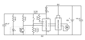
The Circuit
The Code
// Rangefinder navigation with colour sensor
// Code is for MSP430G2553
// Last updated 30-11-2014
//
#include <msp430.h>
// function prototypes
void setup();
void set_motors(int left_speed, int right_speed);
int get_distance();
// main function
int main( void )
{
do
{
// call setup function to configure microcontroller
setup();
__delay_cycles(2000000);
do
{
if (get_distance() > 50) // if there is nothing in front of it but detects white line, reverse
{
P2OUT = 0b00010010;
}
else // else it is being pushed to white line so push back
{
P2OUT = 0b00001001;
__delay_cycles(3000000); // for 1.5 secs
}
}while((P1IN & 0b00100000) < 1); // do this if the robot detects white
do
{
// implement robot behaviour
__delay_cycles(50000);
// is distance greater than 500mm?
if (get_distance() > 500)
{
// yes, so spin around looking for enemy
P2OUT = 0b00010001;
}
else
{
// no, so enemy is straight ahead
P2OUT = 0b00001001;
}
}while(P1IN & 0b00100000); // do this if the robot detects no white
}while(1);
return 0;
}
//
// This function configures the microcontroller. It disables the
// watchdog timer, configures digital i/o, sets up Timer_A0 for
// measuring the duration of the rangefinder echo pulse, sets up
// Timer_A1 for motor PWM, and enables the internal pull up
// resistor on digital input P1.6.
//
void setup()
{
// stop watchdog timer to prevent time out reset
WDTCTL = WDTPW + WDTHOLD;
// configure digital inputs and outputs
P1OUT = 0b00000000; // set P1.0-7 low
P1DIR = 0b10000001; // set P1.0, P1.7 as outputs
P2OUT = 0b00000000; // set P2.0-7 low
P2SEL = 0b00100100; // set pin 10 as TA1.1, pin 13 as TA1.2
P2DIR = 0b00111111; // set P2.0-5 as outputs
// configure Timer_A1 for motor PWM
TA1CTL = TASSEL_2 + ID_0 + MC_1; // Timer_A1: SMCLK clock, input divider=1, "up" mode
TA1CCR0 = 1000; // set Timer_A1 period to 1ms for 1kHz PWM
TA1CCR1 = 1000; // 100% duty cycle initially
TA1CCR2 = 1000; // 100% duty cycle initially
TA1CCTL1 = OUTMOD_7; // select "Reset/Set" output mode
TA1CCTL2 = OUTMOD_7; // select "Reset/Set" output mode
// configure Timer_A0 for measuring rangefinder echo pulse
// select SMCLK clock, input divider=1, "continuous" mode
TA0CTL = TASSEL_2 + ID_0 + MC_2;
// enable pull up resistor on P1.6 for rangefinder echo
P1OUT |= BIT6;
P1REN |= BIT6;
}
//
// This function sets the speed and direction of both motors. The
// first argument controls the left motor. The second argument
// controls the right motor. Each argument can be any integer between
// -100 and +100, where -100 is full speed reverse. +100 is full speed
// forwards.
//
void set_motors(int left_speed, int right_speed)
{
// work out P2OUT value for requested directions
int p2out_value = 0;
if (left_speed > 0) p2out_value += 0b00000001;
if (left_speed < 0) p2out_value += 0b00000010;
if (right_speed > 0) p2out_value += 0b00001000;
if (right_speed < 0) p2out_value += 0b00010000;
// clamp motor speed to allowed range
if (left_speed > 100) left_speed = 100;
if (left_speed < -100) left_speed = -100;
if (right_speed > 100) right_speed = 100;
if (right_speed < -100) right_speed = -100;
// set motor directions and speeds
P2OUT = p2out_value;
TA1CCR1 = 10 * left_speed;
TA1CCR2 = 10 * right_speed;
}
//
// This function measures the distance in mm to the nearest object
// using the rangefinder.
//
int get_distance()
{
// send trigger pulse
P1OUT |= BIT7;
__delay_cycles(20);
P1OUT &= ~BIT7;
// measure echo pulse duration
TA0CTL |= TACLR; // reset timer
while ((P1IN & BIT6) == 0 && TA0R < 12000); // wait for start of echo pulse
TA0CTL |= TACLR; // reset timer
while ((P1IN & BIT6) > 0 && TA0R < 12000); // wait for end of echo pulse
return (TA0R / 6); // return the distance in mm
